
Model:
BL-N2000Brand:
S4A| Product Parameter | Parameter Description |
| S4A Model | BL-N2000 |
| Product Name | Durable Narrow Electric Bolt Lock |
| Working voltage | DC 12V |
| Red | Positive pole(+) |
| Black | Negative pole(-) |
| Current | Starting current is 0.95A and working current is 0.12A |
| Locking delay | 0/3/6/9S |
| LED indication of bolt status | Red light when bolt return and green light when the bolt sticks out Detection of door status |
| Size of stainless steel bolt | Ф12.6MM |
| Sticking-out length | 15MM |
| Size of magnet seat | 84MM(L)×25MM(W) |
| Outer dimension of lock body | 168MM(L)×25MM(W)×37MM(D) |
| Size of decoration panel | 178MM(L)×30MM(W)×0.8MM(D) |
| Size of extension rack | 28MM(L)×23MM(W)×4MM(D) |
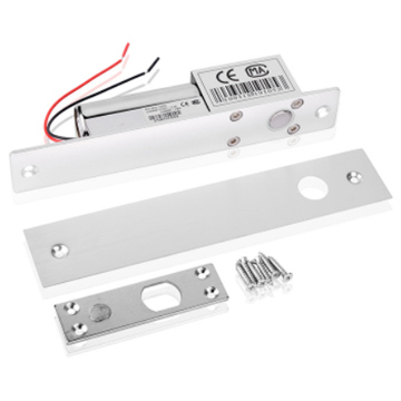
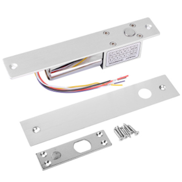
| Accessories for installation | magnet seat (1), decoration panel (1), screw (8), extension rack (2) |

1. Prior to use, please read the instruction carefully, check if major parts are complete, and prior to installation, try to simulate connection as per electric wiring diagram following working way of the electric bolt lock and perform actual installation after the lock works normally.
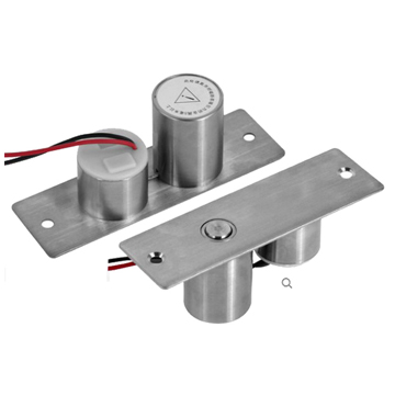
2. The electric bolt lock consists of two major components (1) magnet seat and (2) main body of electric bolt lock. At installation, interval between the magnet seat and positive side of the bolt lock shall not be more than 3mm. Point the bolt hole on magnet seat right at the bolt on the lock and place the magnet in the center of the lock as shown in Figure 1.
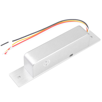
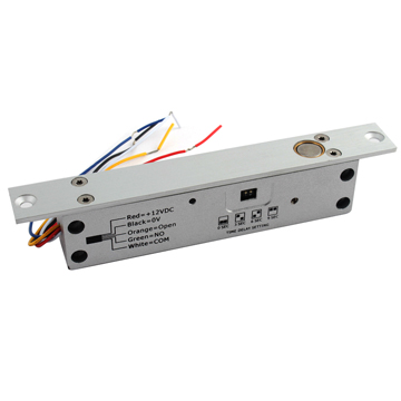
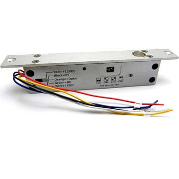
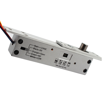
3. Led wires of six colors stick out of the tail part of the lock: red, black, brown, grey, green and orange, as shown in Figure 1. Red wire is for positive pole of power supply of the bolt, which is connected to power of DC12V (+) or positive power line of a controlled power supply. Black wire is for negative pole of power supply of the bolt, which is connected to power of DC12V (-). Brown wire is door-opening control wire of the lock (OPEN). When it is connected to negative pole of power supply, the lock will be opened. It is under control of door-opening button or access control part. Grey, green and orange wires are door detecting wire and they are used to detect if the door is in the open or closed state. Grey wire is public point (COM), green wire is normally open point (NO) and orange wire is normally closed point (NC), as shown in Figure 2. After the door is closed in place, the connecting states of normally open and normally closed points change with each other.

4. DC12V input wiring of electric bolt lock is as shown

5. Adjustment switch for locking delay is set at the side of the lock. The time for locking delay can be
selected by changing position of the toggle switch. The method for setting is as shown

6. The method for installation is as shown

Tags :